


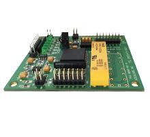
Multi Clock Divider Board
- Category: In-Fixture Electronics
- Manufacturer: Acculogic

The Multi Clock Divider provides a one board solution, capable of accepting a wide frequency bandwidth, for the testing of signal generating devices.
About the Multi Clock Divider Board
The Multi Clock Divider Board (MCD) provides a one board solution, capable of accepting a wide frequency bandwidth, for the testing of signal generating devices such as crystals and oscillators. The low-cost MCD replaces the need for an expensive IEEE controlled counter. Designed for simple installation in the test fixture, it integrates the function of several instruments onto one board.
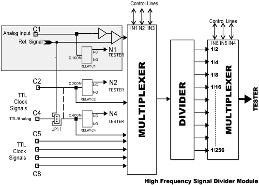
The Multi Clock Divider Board operates by dividing down the input signal to fall within the measurement range of the test system. The divide sequence is selectable through the use of on-board jumpers or programmable by the tester pins under software control. The MCD supports up to 7 different TTL & 1 programmable threshold inputs at frequencies in excess of 100 MHz. This includes CMOS, ECL, PECL, TTL, and analog signals (range of +/- 5V).
The divide sequence programmable range is 1/2, 1/4, 1/8, 1/16, 1/32, 1/64, 1/128 and 1/256. During the oscillator test, the high frequency module can be totally isolated from the tester to minimize the impact of the system capacitance on measurement.
FEATURES
- 100 MHz input frequency bandwidth
- 7 TTL clock inputs
- 1 programmable analog input (+/- 5V)
- High impedance analog input (5MW II 1pF, 500nA/V)
- Programmable divide sequence
- Signal isolation through on board relay
- Crystal and oscillator testing